


Based on extensive use and feedback from our clients, we are thrilled to introduce our third major update to the Virtual Build module within Assembly Planner.
By integrating more Assembly Planner modules into Virtual Build, we have significantly reduced the need to move between the multiple libraries and modules often required to author/edit a full Bill of Process (BOP). Furthermore, to make updating process data easier, workspaces can now include multiple routings and multiple CAD models as is often encountered when working across major sub-assemblies. No need to worry if the Product Engineers still haven't sent the updated CAD files because 3D models are no longer required to create a workspace and author or edit your process in Virtual Build.
Users can now even customize panel views to simultaneously view and edit tasks, tools and parts interactively. Panels can be moved, re-sized, and even floated for use on a 2nd or 3rd monitor.

New MS-Office-style Process, Consumption, CAD Viewer, and Media ribbon menus offer quicker and easier access between Routings, Operations, Activities, and Worksteps.
The Process ribbon menu now supports filtering of workspace rows based on specific models, options, units, and stations. Users can quickly Check-In/Check-Out from the Process tree or menu to create new Operations, Activities, and Worksteps, or to Move and/or Copy Operations, Activities, and Worksteps within or between other Routings. We’ve also added the Autobuild Model–Option functionality to this Process menu, in order to quickly and easily referentially map Activities to product Models and Options within a workspace.

The Consumption ribbon menu provides the ability to consume parts from an mBOM or Library in the normal fashion using the Map to CAD Nodes tool. This approach ensures that the correct instance of the parts consumed in the Activity or Workstep are reflected properly in the CAD model (e.g. – left/right taillight, bolts, pins, etc.).

Optionally, Consumption can also be performed visually using the 3D product CAD model via dragging and dropping CAD nodes to the desired Activity or Work Step in the tree or table. When consumption is performed using the 3D CAD model, instance mapping is automatically performed.
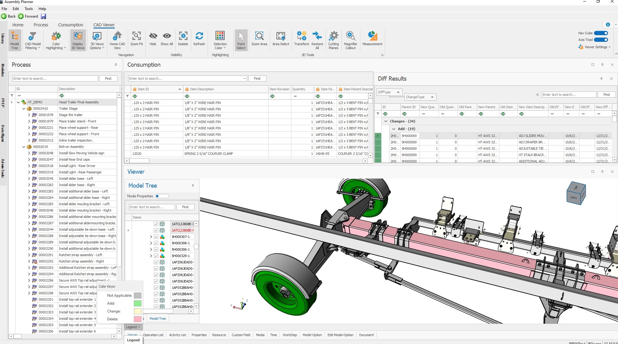
The Assembly Planner BOM Compare feature compares Bill of Material consumption against the Bill of Process, to ensure 100% consumption of parts and assemblies. By integrating this powerful feature inside Virtual Build, users can now add assemblies from an ECO, BOM, or Library from the 3D product CAD model, simply by highlighting those parts and assemblies that need to be consumed, or removed from consumption. Consumption can be added to Activities or Worksteps simply by dragging and dropping parts from either the Diff Results or CAD model tree.
The CAD Viewer ribbon menu gives users the option to filter CAD models showing only components consumed by specific Activity (to view 3D parts consumed by one or more tasks), or all the components consumed UP TO a selected Activity (to show the 3D product virtually build up Activity by Activity). This is very useful for validating the build sequence virtually in a single, integrated environment.
New Color Highlighting tools in the CAD Viewer menu allow users to highlight parts based on results from a BOM Difference Comparison, or by Consumption Status. A new legend in the CAD Viewer panel explains the 3D part color coding used.
The 3D Views tool allows users to select an Activity and quickly capture and associate 3D views. Here, users can update 3D Views and edit 3D View names. Display 3D Views toggles 3D Views on/off in the Viewer panel.

Additionally, the CAD Viewer menu provides tools to Transform parts, add Cutting Planes, add Magnifier Callouts, and perform Measurements.
The SOP CAD Image tool in the Media ribbon menu allows users to select an Activity or Work Step and quickly capture and associate an image from the CAD file. The Consumption CAD Image performs the same way, but attaches the CAD image to the consumption record, which allows the 3D CAD image to be displayed with the part consumption in Proplanner’s Shop Floor Viewer MES system.

The embedded Image Editor supports altering captured images with standard or custom annotations, as well as inserting any images and/or icons. Editing images in this workspace eliminates needing to copy back and forth from PowerPoint, Excel, or Visio. More importantly, our image editor adds edits to your image allowing you to update images in the future without needing to re-annotate them.
The following configurations are recommended to achieve optional performance with the Virtual Build module using the 3D viewer:
-
Computer with dedicated graphics card, 16GB RAM
-
RDP and VPN not recommended because they don’t utilize a dedicated graphics card and therefore performance will be low. This is also true for video authoring and playback.
-
Dedicated PC when working with 3D CAD and Videos.
-
Networks with low connectivity (2MB or 3MB) will cause poor performance. Networks like LAN 100MB+ are recommended.
-